
Magnetic Application Design Service
磁应用设计服务
40 years of expertise. AIC focuses on magnetic-circuit design and magnetic-product application analysis — predicting and solving magnetic-field distribution, efficiency, and material-selection challenges in the earliest design phase.
A dedicated engineering team delivers customised magnetic solutions from concept to volume production. By simulating the magnetic field at the front end of design, we identify performance bottlenecks before tooling — cutting iteration cost and shortening time to market.
From magnetic-material selection and circuit simulation to rapid prototyping and quality control, AIC covers the full application-engineering chain for motors, sensing, transmission, and adsorption products.
Core Design Capabilities
Two integrated disciplines — material expertise and field simulation — working together on every project.
Magnetic Material Selection
磁材精选
Customer-centred selection across NdFeB, SmCo, ferrite, AlNiCo and bonded magnets — balancing magnetic performance, temperature stability, corrosion resistance and cost for each application.
Magnetic Circuit Design
磁路设计
Finite-element simulation to calculate magnetic pull force, flux density and field distribution — delivering optimised circuit topologies and pole arrangements verified before prototyping.
Design Coverage — Single & Combined Circuits
From a single magnetic path tuned to a precise threshold, to multi-path assemblies delivering ultra-high field in a fixed space.
Single Magnetic Circuit
Trigger-field design for chips, and actuation-distance design for proximity or displacement sensors — one magnetic path tuned to a precise threshold.
Combined Magnetic Circuit
High-field assemblies for demanding applications — ultra-high surface field or a fixed-field region in a constrained space, built from multiple magnetic paths working together.
Design Calculation Case Studies
Real FEA-validated designs with measured results — flux density, field uniformity and holding force solved before any tooling is cut.
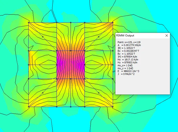
Uniform-Field Cavity
50 × 50 × 50 mm working volume
A near-uniform magnetic field cavity for sensor calibration and magnetic-property testing — field uniformity controlled within 0.07 T across the entire working volume.
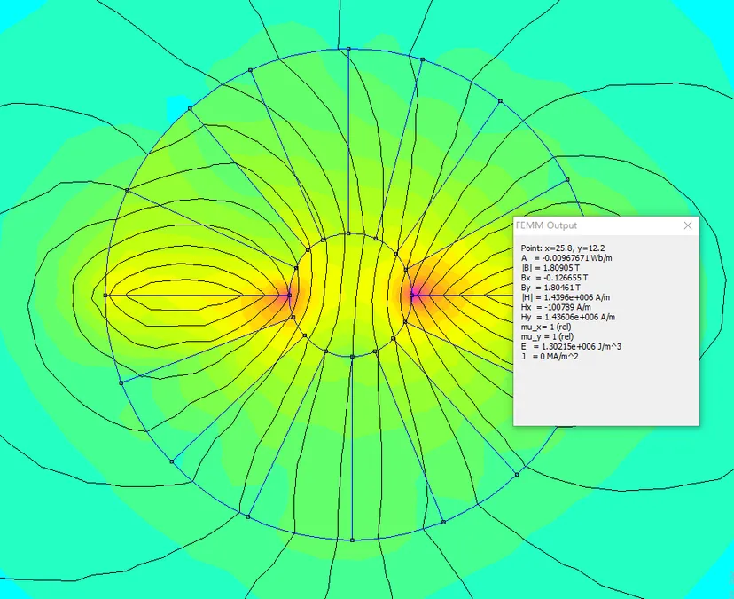
High-Field Compact Region
Ø30 × 50 mm region
Concentrated high-flux design for applications requiring a strong field in a small, fixed space — peak 1.8 T achieved at the region boundary.
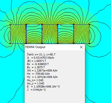
Linear High Surface Field
Linear magnetic circuit
Linear-array design achieving surface magnetic flux density above 1.66 T — for high-sensitivity magnetic sensing and strong surface attraction applications.
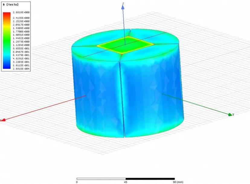
End-Face Holding Assembly
Ø100 × 75 mm end magnet (3D)
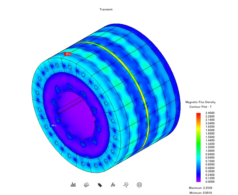
3D transient simulation of an end-face magnetic assembly — 1.6 T center field delivers 641 kgf end-face holding force for heavy-duty workholding and lifting.
3D Transient Field Simulation
Rotors · couplers · multi-pole assemblies
Full 3D transient FEA of rotating magnetic assemblies — flux density contour, peak field and time-varying behaviour solved before any prototype is built, covering motors, couplers and complex multi-pole designs.
Multi-Axis 3D Transient Field Analysis
One rotor assembly, solved along three field components — Y, Z and total magnitude — to fully characterise peak flux, pole balance and leakage before any prototype is built.
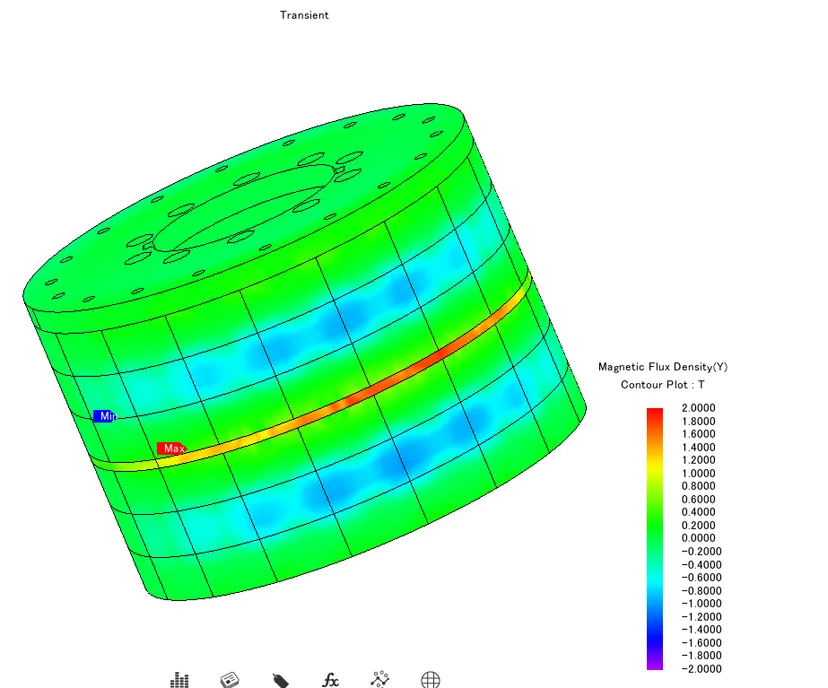 Bᵧ
BᵧY-axis flux density
±2.0 TTransverse field component — reveals the bipolar symmetry of the rotor's outer pole array and confirms field balance between adjacent poles.
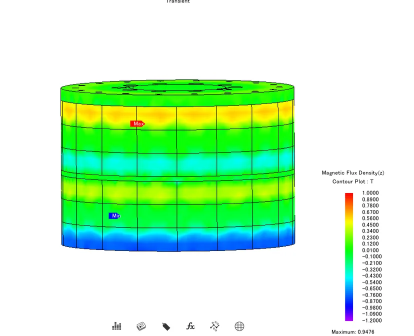 B_z
B_zZ-axis flux density
−1.2 to +1.0 T · peak 0.95 TAxial field component — maps end-face leakage and confirms the active flux length along the rotor axis, critical for stack-length optimisation.
|B|Total flux density magnitude
0 – 2.4 T · peak 2.2539 TVector magnitude contour — pinpoints the absolute peak (2.2539 T) on the outer magnet ring and the near-zero core (0.0018 T), the definitive map for material saturation and back-iron design.
Same component, three orthogonal views — the definitive map for material saturation limits, back-iron sizing and pole-balancing decisions.
How We Design
A predictable five-stage workflow — from requirement capture to validated mass production.
Requirement Analysis
Capture working conditions, space envelope, target force/flux, and thermal environment to define clear design objectives.
Circuit Simulation
FEA modelling of the magnetic field — calculating pull force, induction intensity and leakage to optimise the topology.
Material Selection
Match grade, coating and temperature class from 12 magnetic materials to meet performance and cost targets.
Prototyping & Validation
Rapid prototyping in 3–7 days, with measured magnetic performance and assembly verification.
Mass Production
Stable volume supply with full-process quality control and global magnetic-material sourcing.
Design Scope
What our application-engineering team designs and builds.
Magnetic circuits and magnetic-application product structures
PM transmission systems — magnetic couplers and levitation bearings
Magnetic encoders and scales, with Hall-IC matching
Special-motor PM assemblies — multi-pole rings, radial rings, Halbach arrays
Magnet + plastic / metal component assemblies
Quality inspection and quality-control program design
Test & Measurement Equipment
Precise detection backed by professional instruments — every magnetic parameter is verified, not assumed.
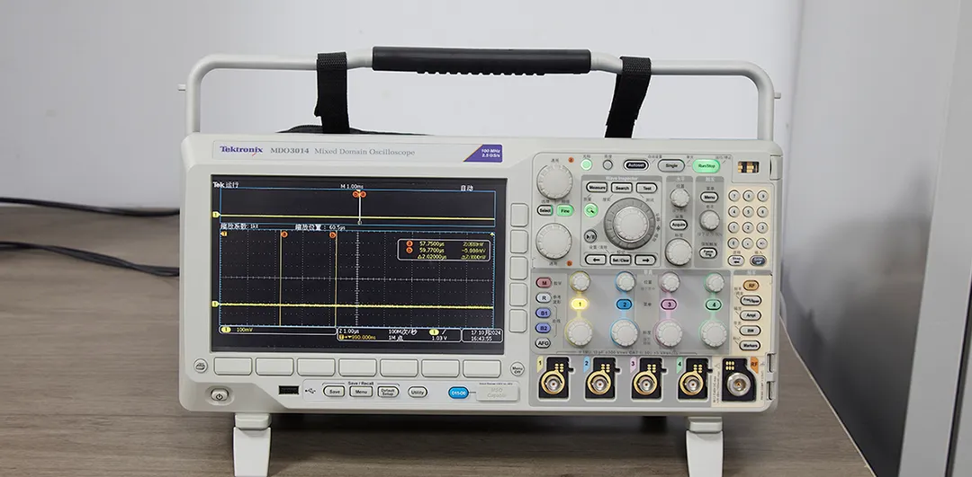
Tektronix MDO3014 Mixed-Domain Oscilloscope
Captures dynamic waveforms of magnetic-sensing and drive signals to validate Hall-IC matching, encoder output and motor behaviour.
Gaussmeter / Teslameter
Surface flux density and field strength
Fluxmeter
Total magnetic flux measurement
Hysteresisgraph (BH tester)
Br, Hcj and (BH)max characterisation
Helmholtz Coil
Magnetic moment & uniform-field testing
CMM Dimensional Inspection
Geometry and tolerance verification
Thermal Cycling Chamber
High/low-temperature stability
Salt-Spray Tester
Coating corrosion resistance
Coating Thickness Gauge
Plating and coating uniformity
Our Quality Principles
Four commitments behind every design we deliver.
Customer First
Every solution starts from your application requirement and constraints.
Precise Detection
Measured verification of magnetic performance at every stage.
Continuous Improvement
Iterative optimisation across design, process and quality.
Total Participation
Cross-functional teams aligned on quality from design to delivery.
Need Magnetic-Circuit Design Support?
Share your application requirement and our engineering team will advise on material selection, circuit topology, feasibility and prototyping. Samples in 3–7 days.
Contact Engineering Team