
Magnetic Sensing Solutions
磁传感解决方案
Hall-effect sensor disc magnets, dual-track rotary encoder discs, and linear magnetic scales — engineered magnetic components for position, speed, and proximity feedback in automation, motor control, and consumer devices.
Magnetic Components for Sensing Systems
Every magnetic sensing system pairs a sensor IC — Hall-effect, magnetoresistive (MR), or an inductive encoder chip — with a permanent magnet that supplies the field it reads. The sensor only converts what the magnet delivers, so the accuracy, consistency, and durability of the magnetic component set the ceiling for the whole measurement chain.
AIC Engineering manufactures the magnetic half of that chain: bipolar Hall-effect sensor disc magnets with 100% automated declination-angle binning, precision multi-track rotary encoder discs that deliver absolute and incremental angle on one carrier, and JC-F series linear magnetic scales supplied as cut-to-length roll stock. Each product family targets a distinct sensing geometry — on-axis rotary, multi-track rotary, and linear displacement.
Because these are engineered components rather than commodity magnets, every family is configured per application: pole count and pitch, declination-angle class, carrier material, coating, and packaging are all matched to the sensor IC and the assembly process it feeds.
Where These Magnets Are Used
Three sensing geometries, three product families — each grounded in the actual product specifications.
Rotary Position & Speed Feedback
BLDC commutation, servo-motor feedback, and rotary encoders read a magnet mounted on or around the shaft. A bipolar Hall sensor disc magnet gives a simple pole-transition signal for commutation and speed pickup; where true angular position is needed, the precision rotary encoder disc carries dual tracks — an incremental main track plus a vernier track with one pole pair fewer — so a single-turn absolute angle is recovered via the Nonius principle, with no homing routine at power-on. Magnetic reading is immune to the oil mist, dust, and chips that blind optical encoder wheels, which is why these discs are specified for machine tools, robotics joints, and CNC rotary tables.
Hall Sensor Disc Magnet & Precision Rotary Encoder
See the dual-track encoder disc rangeLinear Position Sensing
Linear displacement is measured by a Hall/MR read head travelling along a magnetically encoded strip. The JC-F series magnetic scale is encoded at 1 mm, 2 mm, or 5 mm pole pitch and holds an accuracy of ≤ 0.02 mm/m across a −20 to 80 °C operating range. Supplied as 50 m rolls, 10 mm wide and 1.43 mm thick, the strip is cut to length on site, mounts without a precision guideway, and the non-contact read head has no wear — a practical alternative to optical glass scales in machine tools, automation lines, and woodworking or textile machinery where coolant and dust rule out optical gratings.
Linear Encoder (Magnetic Scale)
See JC-F scale models and specsProximity & Switching
Proximity switches, limit switches, liquid-level detection, and throttle/pedal position sensing all trigger a Hall IC with the field of a small bipolar disc magnet. Here the critical parameter is the magnetic declination angle — the deviation of the magnetic axis from the geometric axis — because it sets the switching point's repeatability. AIC controls declination to within ±3° as standard and bins every disc by automated 100% measurement into 1°, 2°, or 3° classes, so automated sensor assembly lines get lot-to-lot angular consistency rather than spot-checked samples.
Hall Effect Sensor Disc Magnet
See angle-binning and packaging optionsProduct Selection & Key Specifications
Specifications as stated on each product page — cells marked — are not published values. Full model-level tables (all 21 MU-series discs, bonded NdFeB AB+Z discs, JC-F models) are on the linked product pages.
| Product | Magnetization / Encoding | Tolerance / Accuracy | Materials & Coating | Op. Temperature |
|---|---|---|---|---|
| Hall Effect Sensor Disc Magnet | Bipolar disc; declination angle binned to 1° / 2° / 3° classes | Declination within ±3° (100% automated measurement); ground to ±0.05 mm | NdFeB / SmCo / Ferrite; Ni / epoxy / Zn coating | — |
| Precision Rotary Encoder (MU series) | Dual-track axial: 32–95 main pole pairs + vernier (one pair fewer); pole pitch ≈ 1.28 / 1.5 / 2.0 mm (MU128 / MU150 / MU200) | Concentricity ±0.02 mm; 0.4 mm detection air gap; surface field 20 mT, 3 mT amplitude at gap | NdFeB / SmCo / bonded magnet on SUS430 stainless or aluminium carrier | −35 … +120 °C |
| Linear Encoder — JC-F Magnetic Scale | Multi-pole strip, 1 / 2 / 5 mm pole pitch (other pitches customisable) | Accuracy ≤ 0.02 mm/m | Flexible magnetic strip, 10 mm wide × 1.43 mm thick, 50 m roll; optional cover strip | −20 … 80 °C |
Design Considerations for Magnetic Sensing
Generic engineering guidance for pairing a magnet with a sensor IC — confirm final values against the sensor datasheet and the product pages above.
Air Gap
Field strength falls off with distance from the magnet face, so the air gap between magnet and sensor die sets the signal amplitude the IC sees. The MU-series encoder discs are specified at a 0.4 mm detection air gap (magnet surface to chip surface), delivering a 3 mT field amplitude at that distance. Keep the gap small, fixed, and accounted for in tolerance stack-up — runout or axial play directly modulates the signal.
Pole Pitch vs. Sensor Resolution
The pole pitch is the spatial period the sensor reads: one north–south cycle per pitch. The sensor IC interpolates within each cycle, so a finer pitch yields more electrical periods per millimetre or per revolution and thus finer native resolution — at the cost of weaker field per pole and tighter gap requirements. Match the pitch to what the sensor IC supports: JC-F scales offer 1, 2, and 5 mm; MU discs offer ≈ 1.28, 1.5, and 2.0 mm series.
Temperature & External Fields
Every permanent magnet loses remanence as temperature rises; verify the operating range against the worst-case environment. The MU encoder discs are rated −35 … +120 °C and the JC-F scale −20 … 80 °C; SmCo is the high-temperature material option where NdFeB falls short. External magnetic fields also matter: fields ≥ 1 mT reduce MU-disc system accuracy, and ≥ 20 mT can permanently damage the disc magnetisation — keep magnetic clamps and stray magnets away.
Magnetization Pattern & Angle Accuracy
The pattern must match the sensing principle: a bipolar disc for on-axis Hall switching and commutation, a multi-pole single track for incremental speed, dual tracks for absolute angle via the Nonius principle. For on-axis Hall discs, the declination angle between the magnetic and geometric axes sets angular repeatability — specify the bin class (1° / 2° / 3°) your sensor IC and assembly process actually need rather than paying for the tightest class by default.
Magnetic Sensing FAQ
Answers grounded in the published specifications of AIC sensing-magnet products.
- What magnet is used with a Hall-effect sensor? +
- A bipolar permanent magnet disc is the standard counterpart for a Hall IC: the sensor reads field polarity and strength at the magnet face and outputs a digital or analog position signal. AIC's Hall sensor disc magnets control the magnetic declination angle to within ±3° as standard, with automated 100% measurement and binning into 1°, 2°, or 3° classes. Bodies are available in NdFeB, SmCo, or ferrite, ground to ±0.05 mm, with Ni, epoxy, or Zn coatings.
- What pole pitches are available for linear magnetic scales? +
- The JC-F series magnetic scale is supplied in 1 mm, 2 mm, and 5 mm pole pitches (models JC-F-01, JC-F-02, JC-F-05), with other pitches customisable on request. All three come as 50 m rolls, 10 mm wide and 1.43 mm thick, with accuracy ≤ 0.02 mm/m over a −20 to 80 °C operating range. An optional cover strip adds environmental protection.
- How does a dual-track magnetic encoder disc provide absolute position? +
- The disc carries an incremental main track plus a vernier track with exactly one pole pair fewer. Comparing the phase of the two tracks resolves the absolute angle within a single turn via the Nonius (vernier) principle — no battery backup and no homing routine at power-on. AIC's standard range covers 21 dual-track models across three pole-pitch series (MU128 ≈ 1.28 mm, MU150 ≈ 1.5 mm, MU200 ≈ 2.0 mm) with 32 to 95 main-track pole pairs.
- What air gap should I design between the magnet and the sensor? +
- As a rule, the gap should be as small and as mechanically stable as the assembly allows, because field amplitude — and therefore signal margin — drops with distance. For a concrete reference, the MU-series encoder discs are specified at a 0.4 mm detection air gap from magnet surface to chip surface, where they deliver a 3 mT field amplitude. Always confirm the operating gap window in the sensor IC datasheet.
- Can magnetic encoders work in oily or dusty environments? +
- Yes — this is their main advantage over optical encoders. Because the read head senses a magnetic field rather than a light pattern, oil mist, dust, and chips do not blind it, which is why magnetic scales and encoder discs are used in machine tools and woodworking machinery. The trade-off is sensitivity to external magnetic fields: fields ≥ 1 mT reduce MU-disc system accuracy, and ≥ 20 mT can permanently damage the disc magnetisation, so keep magnetic fixtures away from the disc.
- What temperature range do magnetic sensing components cover? +
- The MU-series rotary encoder discs are rated for −35 … +120 °C operation, and the JC-F linear magnetic scale for −20 to 80 °C. Where higher temperatures are involved, SmCo is offered as the high-temperature magnet material option for encoder discs, alongside NdFeB for maximum field strength and bonded material for complex shapes.
Related Sensing Magnet Products
Full specifications, model tables, and customisation options for each product family.
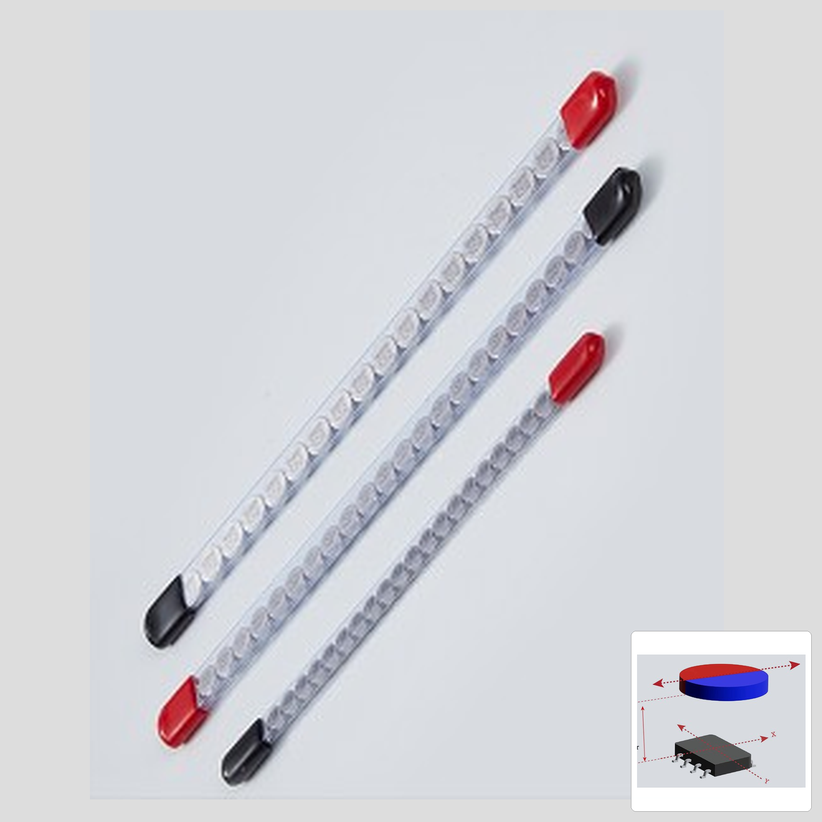
Bipolar discs with ±3° declination control, 100% automated binning into 1°/2°/3° classes, spray-mark traceability, and tube packaging for automated lines.
Hall Effect Sensor Disc Magnet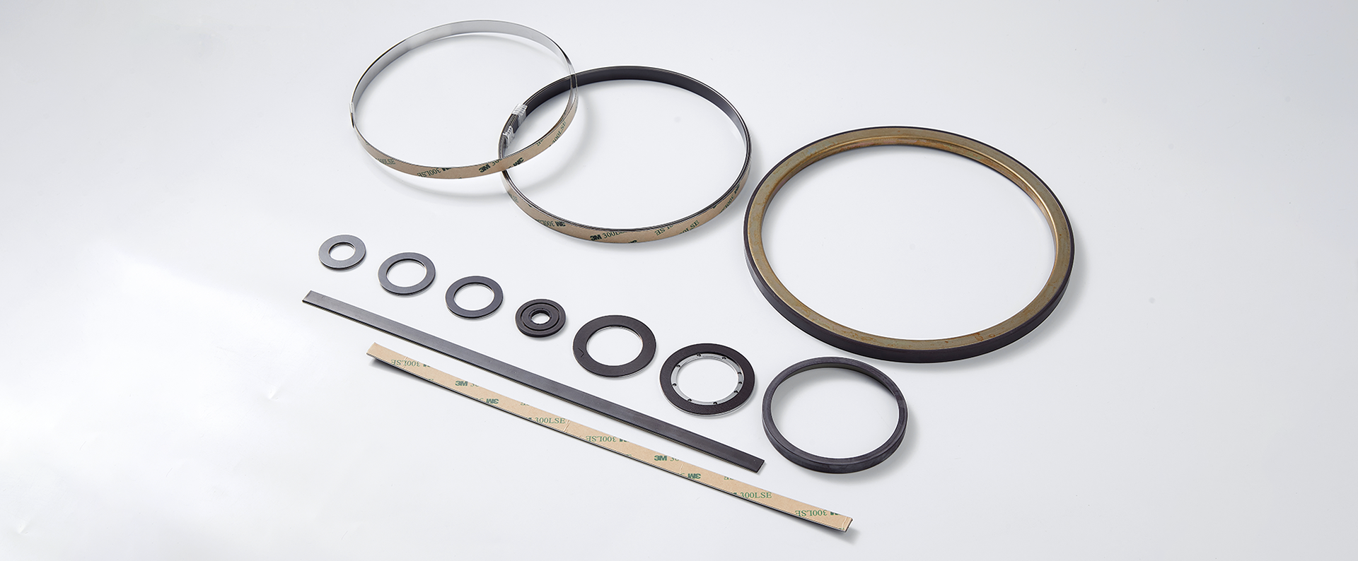
21 standard dual-track absolute discs (MU128/MU150/MU200) plus bonded NdFeB AB+Z incremental rings from Φ39 to Φ207 mm.
Precision Rotary Encoder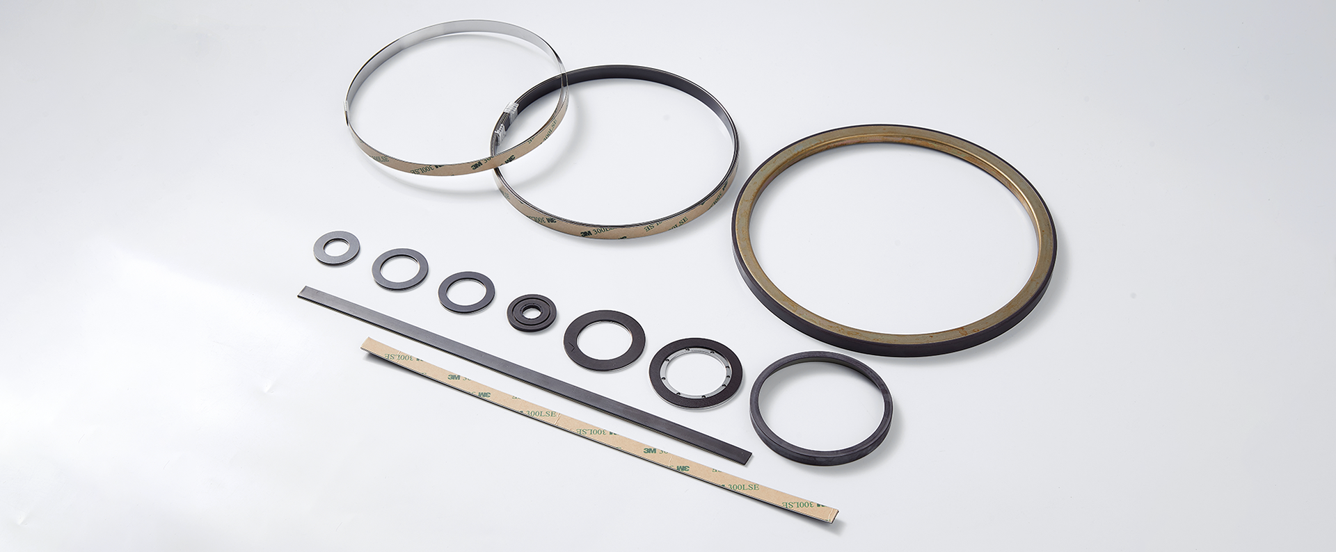
JC-F series scales in 1/2/5 mm pole pitch, 50 m rolls, accuracy ≤ 0.02 mm/m from −20 to 80 °C — cut to length on site.
Linear Encoder — Magnetic ScaleNeed a Magnet for Your Sensing Application?
Send your sensor IC model, required resolution or pole pitch, air gap, and operating temperature — our engineers will match the magnet material, encoding pattern, tolerance class, and packaging to your assembly process.
Discuss Your Sensing Application