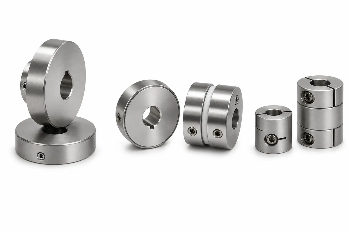
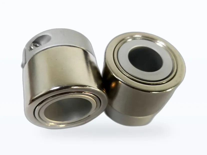
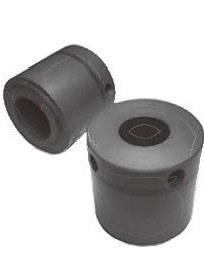
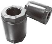
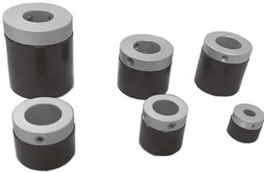
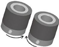
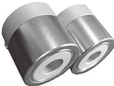
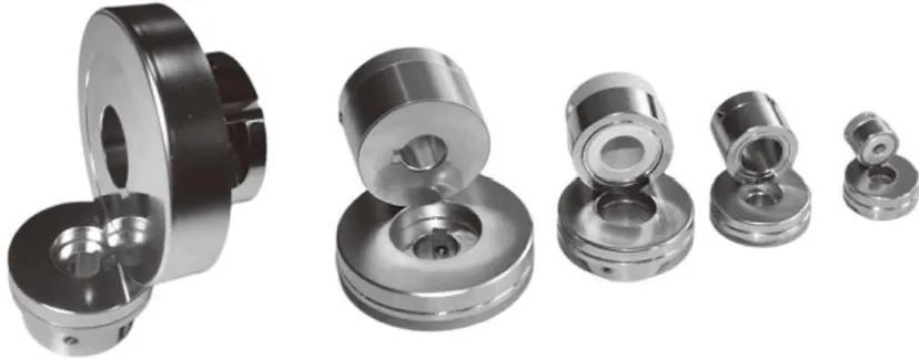
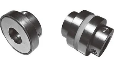
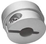
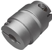
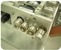
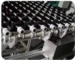
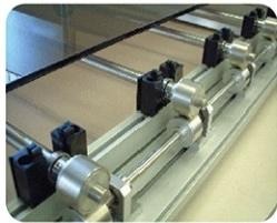
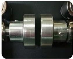
Magnetic Gears transmit torque through the attraction and repulsion of permanent magnets — no physical contact, no friction, no wear particles. Designed for cleanroom production lines (LCD, PDP, PCB, TFT, OLED, Solar Cell) and vacuum chambers where even microscopic contamination is unacceptable, they are a direct replacement for conventional mechanical gears.
Built with sintered NdFeB rare-earth magnets, our MGS / CJ / CS / CDS series deliver industry-leading torque density with virtually zero acoustic output. A built-in torque-limiting function means unexpected overloads cause the gears to slip rather than break — protecting both the gear and the driven equipment.
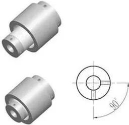
We offer five transmission configurations — orthogonal (90°), parallel, bevel (cone), coaxial face coupling, and magnetic shaft coupling — covering the full range of industrial motion transfer requirements. Corrosion-resistant variants with stainless-steel (316L), titanium, or PVC encapsulation are available for chemical, pharmaceutical, and food-processing applications.
Non-contact transmission generates zero wear particles — ideal for ISO Class 1 cleanrooms.
✦
Ultra-Low Noise
No meshing teeth means virtually silent operation, improving cleanroom working conditions.
✦
Torque Limiting
On overload, gears slip automatically — no mechanical damage, no production stops.
✦
Vacuum Compatible
Operable down to 10⁻⁵ Pa with low outgassing special surface treatments.
✦
Maintenance-Free
No contact surfaces to wear means unlimited service life and zero spare parts cost.
✦
Corrosion Options
SUS316L, titanium or PVC encapsulation available for harsh chemical environments.
Product Classification
Magnetic gears are classified into six main types by transmission direction and structural form:
Orthogonal Drive
MGS Series
Two magnetic gears arranged at 90°. The most compact solution for right-angle power transfer in cleanroom conveyors.
Parallel Drive
CJ Series
Two coplanar gears side by side. Higher torque capacity than orthogonal — the most widely used configuration.
Mixed Drive
MGS + CJ
Combined orthogonal and parallel stages for complex multi-axis transfer paths within a single assembly.
Bevel (Cone) Drive
CS Series
Radial magnetic gear paired with an axial magnetic disc — replaces traditional bevel gears with zero-contact precision.
Face Coupling
CDS / CDQ Series
Coaxial face-to-face disc coupling. Highest torque density in the magnetic gear family, up to 28.5 N·m.
Magnetic Coupling
CI Series
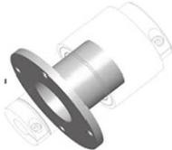
Inner/outer magnet assembly with isolation shell — converts dynamic seals to static seals for zero-leakage pump and reactor drives.
Series & Specifications
Ten standard series covering every transmission configuration — sintered and bonded types, with optional SUS316L / titanium / PVC encapsulation. Torque ratings are measured at the specified air gap; all dimensions in millimetres.
Classification by Magnet Process
Sintered
NdFeB feedstock is vacuum-sintered at high temperature, then precision-machined to specification. High magnetic strength and stable performance for medium-to-high torque applications.
Bonded
Direct injection moulding — short lead time and economical. Slightly weaker than sintered types; suited to light-load, high-volume applications.
The MGS series uses sintered NdFeB rings and is the most common orthogonal (90°) drive. Two gears arranged at right angles enable shaft rotation, conveyor transfer and direction change in a compact footprint — the first choice for right-angle transfer on cleanroom lines.
Dimension codes (values per table below)
Materials & Surface Treatment
Part
Material
Finish
Hub
AL6061
Anodised
Magnet
Sintered NdFeB
Ni plated
MGS set-screw type · standard specifications (model: MGS + OD + poles - bore + hub + flux-ring code)
OD D (mm)
Poles P
Bore d (mm)
Torque N·m (1 mm gap)
L (mm)
l (mm)
N (mm)
M
13
6P
4 / 5 / 6
0.012
15
10
2.5
M3
16
12P
5 / 6 / 8
0.015
13
8
2.5
M3
16
8P
5 / 6 / 8
0.025
13
8
2.5
M3
18
8P
6 / 8
0.05
15
10
2.5
M3
21
6P
6 / 8 / 10 / 12
0.13
21
15
3
M4
21
8P
6 / 8 / 10 / 12
0.11
21
15
3
M4
21
16P
6 / 8 / 10 / 12
0.07
21
15
3
M4
22
18P
6 / 8 / 10 / 12
0.07
18
12
3
M4
25
10P
6 / 8 / 10 / 12 / 15
0.15
22
15
3.5
M4
26
8P
6 / 8 / 10 / 12 / 15
0.20
21
14
3.5
M4
26
10P
6 / 8 / 10 / 12 / 15
0.16
21
14
3.5
M4
26
12P
6 / 8 / 10 / 12 / 15
0.14
21
14
3.5
M4
26
20P
6 / 8 / 10 / 12 / 15
0.05
21
14
3.5
M4
28
8P
8 / 10 / 12 / 15
0.22
25
17
4
M4
29
8P
8 / 10 / 12 / 15
0.25
25
17
4
M4
30
8P
10 / 12 / 15
0.31
25
18
3.5
M4
30
10P
10 / 12 / 15
0.28
25
18
3.5
M4
32
8P
8 / 10 / 12 / 15 / 20
0.40
30
20
5
M4
32
10P
8 / 10 / 12 / 15 / 20
0.32
30
20
5
M4
32
12P
8 / 10 / 12 / 15 / 20
0.28
30
20
5
M4
32
20P
8 / 10 / 12 / 15 / 20
0.09
30
20
5
M4
35
8P
8 / 10 / 12 / 15 / 20
0.55
32
21.5
5.25
M5
35
10P
8 / 10 / 12 / 15 / 20
0.45
32
21.5
5.25
M5
35
12P
8 / 10 / 12 / 15 / 20
0.36
32
21.5
5.25
M5
35
18P
8 / 10 / 12 / 15 / 20
0.25
32
21.5
5.25
M5
39
8P
15 / 17 / 20
0.80
35.8
26.6
4.6
M5
39
12P
15 / 17 / 20
0.48
35.8
26.6
4.6
M5
39
16P
15 / 17 / 20
0.40
35.8
26.6
4.6
M5
40
16P
15 / 20 / 25
0.42
34
24
5
M5
42
12P
15 / 20 / 25
0.74
30
21
4.5
M5
42
18P
15 / 20 / 25
0.42
30
21
4.5
M5
45
10P
15 / 20 / 25 / 30
1.20
35
25
5
M5
45
12P
15 / 20 / 25 / 30
0.95
35
25
5
M5
52
10P
20 / 25 / 30
1.45
35
25
5
M5
65
18P
20 / 25 / 30
1.95
48
35
6.5
M6
Hub: A = 6061 aluminium, S = SUS304. Flux ring: C = reinforced (internal isolation steel ring), X = standard. Standard service temperature 0–80°C, 150°C on request.
Model code: Model code: MGS 32 08P -15 A C → MGS3208-15AC = 32 mm OD, 8 poles, 15 mm bore, aluminium hub, reinforced type.
Standard range shown; dimensions, pole counts and fixings can be customised on request.
MGS Series · Orthogonal, Clamp Type (-CP)
Clamp (-CP) fixing replaces set screws: uniform clamping force, no shaft marking and easier assembly — ideal where frequent maintenance is needed or the shaft surface must stay unmarked. Transmission performance matches the set-screw type.
Dimension codes (values per table below)
Materials & Surface Treatment
Part
Material
Finish
Hub
AL6061
Anodised
Magnet
Sintered NdFeB
Ni plated
MGS clamp type · standard specifications (same model code plus -CP for clamp fixing)
OD D (mm)
Poles P
Bore d (mm)
Torque N·m (1 mm gap)
L (mm)
l (mm)
N (mm)
M
21
6P
8 / 10 / 12
0.13
25
15
5
M2.5
21
8P
8 / 10 / 12
0.11
25
15
5
M2.5
22
18P
8 / 10 / 12
0.07
20
12
4
M2.5
25
10P
8 / 10 / 12
0.15
22
15
3.5
—
26
8P
8 / 10 / 12
0.20
24
14
5
M3
26
10P
8 / 10 / 12
0.16
24
14
5
M3
26
20P
8 / 10 / 12
0.05
24
14
5
M3
28
8P
8 / 10 / 12 / 15
0.22
25
17
4
M3
29
8P
8 / 10 / 12 / 15
0.25
25
17
4
M3
30
8P
10 / 12 / 15
0.31
27.5
18
4.75
M3
30
10P
10 / 12 / 15
0.28
27.5
18
4.75
M3
32
8P
10 / 12 / 15
0.40
30
20
5
M3
32
10P
10 / 12 / 15
0.32
30
20
5
M3
32
12P
10 / 12 / 15
0.28
30
20
5
M3
32
20P
10 / 12 / 15
0.09
30
20
5
M3
35
8P
10 / 12 / 15 / 20
0.55
32
21.5
5.25
M3
35
10P
10 / 12 / 15 / 20
0.45
32
21.5
5.25
M3
35
12P
10 / 12 / 15 / 20
0.36
32
21.5
5.25
M3
35
18P
10 / 12 / 15 / 20
0.36
32
21.5
5.25
M3
39
8P
15 / 17 / 20 / 25
0.80
37
26.6
5.2
M4
39
12P
15 / 17 / 20 / 25
0.58
37
26.6
5.2
M4
39
16P
15 / 17 / 20 / 25
0.40
37
26.6
5.2
M4
40
16P
12 / 15 / 20 / 25
0.42
34
24
5
M4
42
12P
15 / 20 / 25 / 30
0.74
30
21
4.5
M4
42
18P
15 / 20 / 25 / 30
0.42
30
21
4.5
M4
45
10P
15 / 20 / 25 / 30
1.20
35
25
5
M4
45
12P
15 / 20 / 25 / 30
0.95
35
25
5
M4
52
10P
20 / 25 / 30 / 35
1.45
37
25
5
M5
65
18P
20 / 35 / 40
1.95
50
35
7.5
M5
Hub: A = 6061 aluminium, S = SUS304; finish: C = reinforced, X = standard; fixing: clamp (CP). Standard service temperature 0–80°C, 150°C on request.
Model code: Model code: MGS3208-15AC-CP = 32 mm OD, 8 poles, 15 mm bore, aluminium hub, steel flux ring, clamp fixing.
MD Series · Corrosion-Resistant Encapsulation (316L / Ti)
The MD series fully encapsulates hub and magnet ring in SUS316L or titanium with sealed seams for long-term service in corrosive chemical, pharmaceutical and food environments. MDT = orthogonal drive, MDP = parallel drive.
Dimension codes (values per table below)
MDT / MDP standard specifications
OD D (mm)
Poles P
Bore d (mm)
L (mm)
l (mm)
M
Orthogonal torque N·m (1 mm gap)
Parallel torque N·m (1 mm gap)
22
8P
8 / 10 / 12
22
8
M4
0.09
0.13
27
8P
8 / 10 / 12
22
7.5
M4
0.14
0.30
27
10P
8 / 10 / 12
22
7.5
M4
0.11
0.26
29
8P
10 / 12 / 15
25
9
M4
0.20
0.36
30
8P
10 / 12 / 15 / 16
25
9
M4
0.23
0.38
30
10P
10 / 12 / 15 / 16
25
9
M4
0.20
0.35
31
8P
10 / 12 / 15 / 20
25
9
M4
0.25
0.40
31
10P
10 / 12 / 15 / 20
25
9
M4
0.23
0.39
36
8P
10 / 12 / 15 / 20
32
11
M5
0.40
0.78
36
10P
10 / 12 / 15 / 20
32
11
M5
0.35
0.72
36
12P
10 / 12 / 15 / 20
32
11
M5
0.30
0.58
40
12P
10 / 15 / 20
36.5
13
M5
0.58
0.98
46
10P
15 / 20 / 25
37
13
M5
0.83
1.20
53
10P
20 / 25 / 30
37
13
M5
0.95
1.80
Encapsulation: S = SUS316L, T = titanium. Standard service temperature 80°C, 150°C on request.
Model code: Model code: MDT3608-15S = orthogonal drive, 36 mm OD, 8 poles, 15 mm bore, SUS316L encapsulation.
MP Series · Full PVC Encapsulation (Acid/Alkali Proof)
The MP series fully encapsulates hub and magnet ring in imported PVC with sealed seams, withstanding long-term exposure to strong acids and alkalis — ideal for wet-process equipment. MPT = orthogonal drive, MPP = parallel drive.
Dimension codes (values per table below)
MPT / MPP standard specifications
OD D (mm)
Poles P
Bore d (mm)
L (mm)
l (mm)
M
Orthogonal torque N·m (0.5 mm gap)
Parallel torque N·m (0.5 mm gap)
23
8P
8 / 10
26
10.5
M4
0.07
0.10
28
8P
8 / 10 / 12
25
10
M4
0.11
0.23
30
8P
8 / 10 / 12 / 15
30
11.5
M5
0.14
0.31
32
10P
8 / 10 / 12 / 15
31
12
M5
0.18
0.33
37
8P
10 / 12 / 15 / 20
34.5
14
M5
0.32
0.59
41
8P
15 / 20
39
16
M5
0.48
0.77
44
12P
15 / 20
34
13.5
M5
0.45
0.72
47
10P
15 / 20 / 25
38
15.5
M5
0.78
0.98
55
10P
20 / 25 / 30
28
15.5
M5
0.87
1.54
Note: due to PVC material limits, keep service temperature within 60°C. Custom dimensions on request.
Model code: Model code: MPT3008-12 = orthogonal drive, 30 mm OD, 8 poles, 12 mm bore, PVC encapsulated.
CM-PE Series · Bonded, POM Clamp
The CM series uses bonded (injection-moulded) NdFeB rings — one-piece moulding, short lead time and economical, with slightly lower magnetic strength than sintered types. The POM clamp hub grips evenly without marking the shaft; ideal for light-load, high-volume orthogonal drives.
Dimension codes (values per table below)
CM-PE · POM hub, clamp fixing
Model
OD D (mm)
Poles P
Bore d (mm)
C (mm)
L (mm)
Torque N·m (1 mm gap)
CM2106P-dPE
21
6P
10
15
26.5
0.11
CM2108P-dPE
21
8P
10
15
26.5
0.07
CM2106PL-dPE
21
6P
10
30
41.5
0.15
CM2608P-dPE
26
8P
8 / 10 / 12 / 15
14
25.5
0.12
CM2610P-dPE
26
10P
8 / 10 / 12 / 15
14
25.5
0.10
CM3208P-dPE
32
8P
10 / 15 / 20
20
32
0.20
CM3210P-dPE
32
10P
10 / 15 / 20
20
32
0.16
CM3508P-dPE
35
8P
10 / 12 / 15 / 20
21.5
33
0.27
CM3510P-dPE
35
10P
10 / 12 / 15 / 20
21.5
33
0.23
CM3512P-dPE
35
12P
10 / 12 / 15 / 20
21.5
33
0.20
CM4212P-dPE
42
12P
10 / 12 / 15 / 20 / 25
21
32.5
0.30
Model code: Model code: CM3508P-20PE = 35 mm OD, 8 poles, 20 mm bore, POM hub, electrophoretic-coated ring; the L suffix denotes the long type.
Bonded series OD, pole count and bore can be customised on request.
CM-BE-S Series · Bonded, Nut-Lock Fixing
Nut-lock fixing: a polygon nut hub locks onto the shaft — simple, vibration-resistant and reliable for orthogonal drives.
Dimension codes (values per table below)
CM-BE-S · nut-lock fixing
Model
OD D (mm)
Poles P
Bore d (mm)
C (mm)
L (mm)
Torque N·m (1 mm gap)
CM3508P-dBE-S
35
8P
15 / 20
32
46
0.38
CM3512P-dBE-S
35
12P
15 / 20
32
46
0.21
Model code: Model code: CM3508P-20BE-S = 35 mm OD, 8 poles, 20 mm bore, nut-lock fixing.
CM-AM Series · Bonded, Aluminium Set-Screw Hub
Aluminium set-screw hub: 6061 aluminium or SUS304 hub with set-screw fixing, covering OD 16–52 mm — the widest range among bonded-series fixings.
Dimension codes (values per table below)
CM-AM · aluminium hub, set-screw fixing
OD D (mm)
Poles P
Bore d (mm)
C (mm)
L (mm)
M
Torque N·m (1 mm gap)
16
8P
6 / 8
8
13
M2.5
0.04
21
6P
8 / 10 / 12
15
21
M4
0.10
21
8P
8 / 10 / 12
15
21
M4
0.07
26
8P
8 / 10 / 12 / 15
14
21
M4
0.12
26
10P
8 / 10 / 12 / 15
14
21
M4
0.10
28
8P
10 / 12 / 15
17
24
M4
0.15
30
8P
10 / 12 / 15 / 16
18
25
M4
0.18
30
10P
10 / 12 / 15 / 16
18
25
M4
0.15
32
8P
10 / 12 / 15 / 20
20
28
M4
0.20
32
10P
10 / 12 / 15 / 20
20
28
M4
0.16
35
8P
10 / 12 / 15 / 20
21.5
30
M5
0.27
35
10P
10 / 12 / 15 / 20
21.5
30
M5
0.23
35
12P
10 / 12 / 15 / 20
21.5
30
M5
0.20
42
12P
10 / 15 / 20
21
29
M5
0.30
45
10P
15 / 20 / 25
25
35
M5
0.55
52
10P
20 / 25 / 30
22
30
M5
0.70
Hub: A = 6061 aluminium, S = SUS304; set-screw fixing standard — add -CP for clamp fixing.
Model code: Model code: CM3508P-20AM = 35 mm OD, 8 poles, 20 mm bore, aluminium hub with set-screw fixing.
CJ Series · Parallel Drive
Parallel drive connects two parallel shafts, with adjacent gears counter-rotating. The CJ series is the most widely used configuration and delivers higher torque than orthogonal drives of the same diameter.
Dimension codes (values per table below)
CJ parallel drive · standard specifications
Model
OD A (mm)
Bore D (mm)
L (mm)
G (mm)
F (mm)
M
Poles P
Torque N·m (1 mm gap)
CJ1308P-D
13
10 / 15 / 20
15
10
2.5
M2.5
10P
2.20
CJ1612P-D
16
6 / 8
13
8
2.5
M2.5
12P
0.05
CJ2108P-D
21
8 / 10 / 12
21
15
3
M4
8P
0.20
CJ2218P-D
22
8 / 10 / 12
18
12
3
M4
18P
0.13
CJ2412P-D
24
10 / 12
19
12
3.5
M4
12P
0.40
CJ2612P-D
26
8 / 10 / 12 / 15
21
14
3.5
M4
12P
0.45
CJ2618P-D
26
8 / 10 / 12 / 15
21
14
3.5
M4
18P
0.21
CJ2812P-D
28
10 / 12 / 15
25
14
3.5
M4
12P
0.32
CJ3010P-D
30
8 / 10 / 12 / 15
25
18
3.5
M4
10P
0.39
CJ3210P-D
32
10 / 12 / 15
30
20
4
M4
10P
0.80
CJ3512P-D
35
10 / 12 / 15 / 20
32
21.5
5.25
M5
12P
1.10
CJ3518P-D
35
10 / 12 / 15 / 20
32
21.5
5.25
M5
18P
0.70
CJ3916P-D
39
10 / 15 / 20
35.8
26.5
5
M5
16P
1.50
CJ4510P-D
45
10 / 15 / 20
34
25
4
M5
10P
2.20
D in the model code stands for the bore option — specify bore size when ordering.
Model code: Model code: CJ3010P-15AC = parallel drive, 30 mm OD, 10 poles, 15 mm bore, aluminium hub, reinforced type.
Standard range can be ordered with clamp fixing (-CP) or SUS / titanium / PVC encapsulation.
CS Series · Bevel (Cone) Drive
The CS series replaces traditional bevel gears: the radial poles of a magnetic gear interact with the axial poles of a magnetic disc. Each set comprises a gear and a disc, with ratios of 1:1, 5:4, 4:3 and 2:1 available.
Dimension codes (values per table below)
CS bevel drive · standard specifications
Model
Disc OD A (mm)
Gear OD B (mm)
Disc bore C (mm)
Gear bore D (mm)
E (mm)
F (mm)
Ratio
Torque N·m (1 mm gap)
Torque N·m (5 mm gap)
CS3026-CD
30
26
8 / 10 / 12 / 15
8 / 10 / 12 / 15
16
21
1:1
0.45
0.04
CS3530-CD
35
30
8 / 10 / 12 / 15
10 / 12 / 15 / 16
16
20
5:4
0.70
0.06
CS4735-CD
47
35
12 / 15 / 20
10 / 12 / 15 / 20
21
25
1:1
1.30
0.18
CS6045-CD
60
45
15 / 20 / 25
15 / 20 / 25
25
30
1:1
2.50
0.34
CS6545-CD
65
45
15 / 18 / 20 / 25
15 / 20 / 25
24
30
1:1
3.10
0.80
CS7552-CD
75
52
18 / 20 / 25
15 / 20 / 25 / 30
27
33
1:1
4.20
1.10
CS6050-CD
60
50
15 / 18 / 20 / 22
15 / 20 / 25 / 30
33
45
1:1
2.60
0.90
CS6080-CD
60
80
15 / 18 / 20 / 22
20 / 25 / 30 / 35
33
45
4:3
6.00
1.40
CS60100-CD
60
100
15 / 18 / 20 / 22
20 / 25 / 30 / 35
33
45
2:1
7.10
1.75
Model code: Model code: CS6545-2520 = bevel drive with 65 mm disc OD / 25 mm disc bore and 45 mm gear OD / 20 mm gear bore.
Custom torque, temperature rating, fixing, envelope dimensions, ratio and encapsulation available on request.
CDS Series · Coaxial Face Coupling
The CDS series integrally multi-pole-magnetises NdFeB magnets on a S45C steel body — strong field, high transmission torque and economical. Among the highest torque-density products in the magnetic-drive family.
Dimension codes (values per table below)
CDS face coupling · standard specifications
Model
OD A (mm)
Bore B (mm)
Height C (mm)
D (mm)
E (mm)
F (mm)
G (mm)
H (mm)
M
Torque N·m (1 mm gap)
Torque N·m (5 mm gap)
CDS12-B
12
4 / 5 / 6
16
12
—
—
—
—
M3
0.05
—
CDS24-B
24
6 / 8 / 10
18
18
10
5
6
3.2
M4
0.42
0.04
CDS28-B
28
6 / 8 / 10
18
20
10
5
10
4.2
M4
0.75
0.12
CDS32-B
32
8 / 10 / 12
18
24
10
5
12
4.2
M5
1.95
0.32
CDS38-B
38
8 / 10 / 12 / 15
18
28
10
5
15
5.2
M5
2.98
0.82
CDS43-B
43
12 / 15 / 20
20
30
12
5
15
5.2
M5
3.80
1.20
CDS50-B
50
12 / 15 / 20
22
34
13
6
20
5.5
M5
4.20
1.50
CDS63-B
63
15 / 18 / 20 / 25
25
36
15
6
26
5.5
M5
11.0
4.50
CDS68-B
68
15 / 18 / 20 / 25
30
40
18
8
30
6.2
M5
16.2
7.20
CDS78-B
78
18 / 20 / 25 / 30
32
42
18
10
33
6.2
M5
18.5
10.0
Model code: Model code: CDS32-10 = face coupling, 32 mm OD, 10 mm bore.
Standard parts are keyway-free with set-screw fixing; keyway or clamp fixing on request.
CDQ Series · Encapsulated Face Coupling
The CDQ series builds on the CDS with full encapsulation in stainless steel, aluminium, PVC or titanium for superior water and corrosion resistance in humid, corrosive and clean environments.
Dimension codes (values per table below)
CDQ encapsulated face coupling · standard specifications
Model code: Model code: CDQ40-12-A = encapsulated face coupling, 40 mm OD, 12 mm bore, aluminium encapsulation.
CI Series · Magnetic Coupling (Canister Type)
The CI series comprises inner and outer magnet assemblies separated by an isolation shell: the inner magnet connects to the driven part, the outer to the drive. Beyond the cushioning of a flexible coupling, it converts dynamic seals into static seals for zero leakage — widely used on chemical pumps and reactor drives.
Dimension codes (values per table below)
CI inner/outer magnet · specifications
Model
ΦA
ΦB
C
ΦD
Φa
Φb
Φd
E
F
G
H
I
J
K
L
M
P
Torque N·m
CI045
45
38
50
19
33
27
12
32
6
21.8
38
4
5
4
60
M4
M3
2
CI060
60
47
58
24
43
35
15
38
8
27.3
46
4
6
5
70
M5
M4
5.4
CI080
80
58
65
28
58
48
20
40
8
31.3
49.5
5.5
7
6
80
M6
M5
11.5
CI100
100
70
100
35
72
58
25
72
10
38.3
83
6
8.5
7
117
M8
M6
43.8
CI120
120
70
105
35
86
70
30
72
10
38.3
86
6
8.5
7
125
M8
M8
84
All dimensions in mm
Matching isolation shell specifications
Shell (for)
ΦA
ΦB
C
ΦD
E
L
P (mounting)
CI045
65
31
37.5
29
5
38.5
Φ4.5 / P.C.D 55
CI060
90
40
46.5
38
9
47.5
Φ5.5 / P.C.D 77
CI080
115
55
49
51
8
51
Φ6.6 / P.C.D 99
CI100
142
68
84
62
10
84
Φ8.6 / P.C.D 122
CI120
165
82
86
74
10
88
Φ8.6 / P.C.D 145
All dimensions in mm
Model code: Isolation shells are supplied as a set with the coupling; stainless steel or titanium selected per medium.
Standard service temperature 80°C; 180°C and 300°C versions and full custom builds on request.
Magnetic Circuit Design
An internal magnetic-isolation steel ring concentrates flux on the outer surface of the magnetic ring — boosting torque by 20% versus comparable products.
+20%Torque vs comparable products
1
Pole Circuit Simulation
FEA of the multi-pole ring validates flux density and pole arrangement before tooling.
2
Magnetic Ring
Sintered NdFeB ring with an internal magnetic-isolation steel sleeve to redirect flux outward.
3
Angular Waveform
Surface flux B(G) measured vs rotation angle — sine symmetry confirms uniform multi-pole magnetisation.
4
Magnetic Gear Wheel
Finished magnetic rotor with optimised outer-field strength for non-contact torque transfer.
How to Select
Follow these seven steps to size a magnetic gear for your application — our engineers can complete the calculation for you.
1Select the transmission direction (orthogonal / parallel / bevel / face / canister)
2Select the product type (sintered / bonded / encapsulation)
3Calculate the quantity from workpiece size and transfer distance
4Calculate the load torque
5Select the gear OD from the required torque per stage
6Select the bore size to match the shaft
7For special applications (acid/alkali resistance, sensing interference, etc.) state requirements when ordering
Handling Precautions
Depending on the spec and required torque, set the gap between 0.5–3 mm, and never below 0.3 mm.
Never re-machine the magnet section — the magnet may crack or shatter.
Avoid letting two magnetic gears strike each other — strong impacts can damage them.
The magnetic field may affect phones, magnetic cards and mechanical watches — keep them at a distance.
Non-contact transmission is not suited to very high speeds — maximum 1500 RPM.
Answers to common questions about our magnets, customisation, ordering and shipping.
What is a magnetic gear?
+
A magnetic gear transmits torque between input and output rotors via interacting magnetic fields instead of meshing teeth — contactless, lubrication-free, and inherently overload-safe (rotors slip instead of breaking teeth).
What are the advantages of magnetic gearing?
+
No physical contact means no wear, no lubrication, low noise, and overload protection; magnetic gears also isolate vibration and tolerate misalignment better than mechanical gears.
Where are magnetic gears used?
+
Typical applications include precision drives, clean/sterile environments, aerospace and robotics where lubrication-free, low-wear, overload-safe torque transmission is required.
Need a Custom Specification?
Our engineering team can customise dimensions, series, bore size, surface treatment and encapsulation material to your exact requirements.