
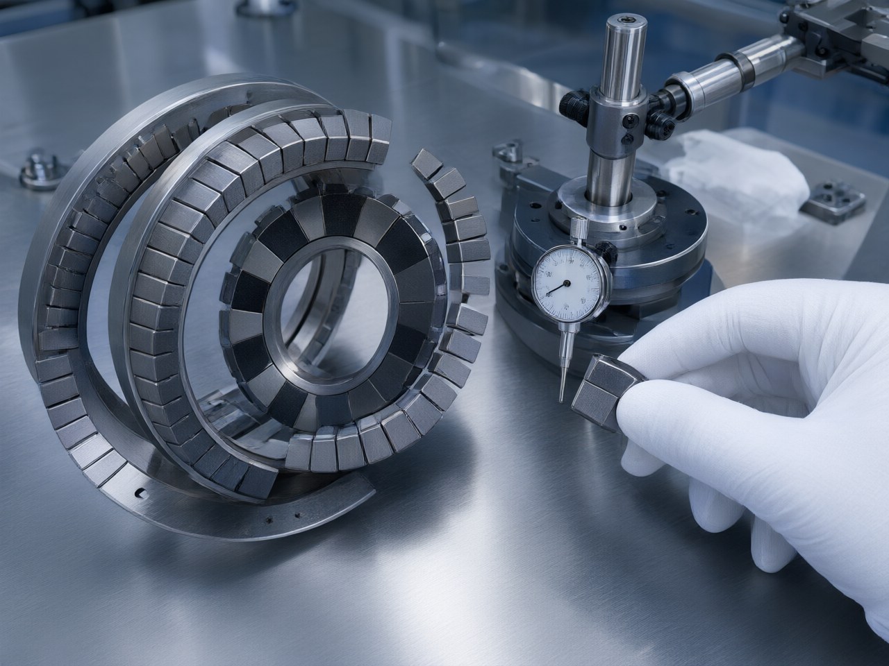
Mechanical gears introduce backlash and wear debris, which are completely unacceptable in precision and cleanroom applications. Magnetic gears solve this problem by providing zero mechanical backlash through non-contact torque transmission. However, they introduce torsional…
Backlash and Efficiency Performance of Magnetic Gears in Precision Transmission
A magnetic gear has zero mechanical backlash because its rotors never touch, so there is no tooth-clearance dead band. It is still compliant, though. The output lags the input by a load-dependent angle that you can predict and correct. Efficiency depends on speed and construction. The losses are eddy currents and hysteresis in the magnets and iron, plus bearings and windage. For precision drives the design job has three parts: size the slip torque so the operating load sits in a stiff region of the torque–angle curve, keep conductive parts out of strong alternating fields, and close the loop at the output if absolute position matters.
A Precision Indexing Drive
A cleanroom equipment team needs a 1:1 parallel-axis transfer between a servo and an indexing spindle. The existing meshing transfer sheds particles and shows backlash as settling error on reversal. They are looking at a catalogue parallel-axis magnetic gear: Ø35 mm, 12 poles, 1:1. Wheel B slip torque is 0.764–1.38 N·m at a 1 mm gap, with magnets 5.25 mm thick by 21.5 mm wide (AIC Engineering product specifications [5]). The steady load in this scenario is about 0.2 N·m.
With the teeth gone, the reversal dead band and the wear debris go with them. Two questions remain: how far the output winds up under load, and where the energy goes.
Zero Backlash Still Means Torsional Compliance
To first order, the torque of a synchronous magnetic coupling or a parallel-axis magnetic gear varies sinusoidally with the mechanical load angle θ in radians:
Here p is the number of pole pairs on the shaft of interest. Near zero load the torsional stiffness is approximately in N·m/rad.
Applied to the case, take the conservative end of the published slip range, T_max = 0.764 N·m, with p = 6 for a 12-pole wheel. At 0.2 N·m, arcsin(T_load/T_max) is about 0.265 rad, so the windup is roughly 0.044 rad, or about 2.5° at the output. Treat this as a first-order estimate. Real gears have harmonics, end effects and tolerance spread, which is why the catalogue gives a range.
For a precision drive this has several consequences:
- The error is repeatable and has no dead zone, so feed-forward or output-side feedback can remove it. Backlash flips sign on reversal.
- Load ratio sets both stiffness and margin. Moving to the Ø50 mm, 16-pole, 1:1 pair (wheel B slip 1.73–3.11 N·m, p = 8) lowers the load ratio and raises stiffness, in a larger envelope.
- More pole pairs increase stiffness per unit of slip torque. They also raise the field alternation frequency at a given speed, and that feeds directly into the loss discussion below.
Where Magnetic Gear Efficiency Is Lost
There is no tooth sliding friction. What remains depends on construction and speed:
| Loss source | Parallel-axis magnetic gear | Coaxial (flux-modulated) magnetic gear | Design lever |
|---|---|---|---|
| Eddy current in conductive parts | Low if no metal sits in the gap | Modulator ring and any containment sleeve see alternating flux | Laminated or non-conductive modulator material; avoid metal sleeves in the gap |
| Magnet eddy loss | Rises with speed and pole count | Rises with speed; high-speed rotor most exposed | Segment magnets; limit pole count at high speed |
| Iron hysteresis and eddy | Back-iron, if fitted | Modulator pole pieces, back-iron | Material and lamination choice |
| Bearings, seals, windage | Two independent shafts | Three concentric members | Bearing selection and preload |
| Published torque example | Wheel B slip 1.87–3.37 N·m, Ø35/12 driving Ø70/24, 2:1, 1 mm gap | Low-speed-side pull-out 18.1–27.5 N·m, 2/7 pole pairs, 3.5:1, 40 mm length | Match published torque and envelope to the duty |
Torque figures: AIC Engineering product specifications, https://www.aicmagnetics.com [5].
Losses from alternating fields grow quickly with frequency. Many indexing and positioning duties are low speed; a magnetic gear then generally runs cool, and bearings make up much of the loss. In continuous high-speed duty, eddy loss in modulators, magnets and any conductive barrier dominates both efficiency and magnet temperature. Check magnet temperature before committing to a pole count. The coaxial topology is the flux-modulated gear analysed by Atallah and co-authors [1][2]; its efficiency is set by that loss balance at the speed you run.
Overload Slip: Protection With a Position Cost
When load exceeds the limit, the gear slips instead of breaking. This torque-limiting behaviour is listed by AIC as a core property of magnetic gears used in precision drives, pumps and cleanroom equipment [5]. After a slip event the rotors re-lock at another stable alignment, so the output can be offset by an integer multiple of 360°/p on that shaft. In an indexing system that is a silent position error unless something detects it. An output-side encoder, or a homing routine triggered by a following-error alarm, handles this.
Where the Approach Breaks Down
Some applications should not use a magnetic gear, or need extra measures:
- If the specification calls for very high static stiffness with no feedback, such as open-loop micro-positioning under varying load, magnetic compliance will consume the error budget.
- Heat from eddy loss or the environment pushes the magnet operating point toward irreversible demagnetization. Any loss of strength lowers T_max and therefore also lowers stiffness.
- The gap is the most sensitive parameter. Non-magnetic layers such as paint, plating and adhesive tape have to be counted as gap. Bearing wear or shaft deflection that opens the gap reduces torque.
- Exposed magnets attract ferrous debris and loose steel parts. In open machine environments, plan for shrouding or a sealed barrier.
Design Review Points Before Release
- Load ratio T_load/T_max at worst-case temperature, and the resulting windup angle and stiffness.
- Assembled gap including coatings and sleeves, with the tolerance stack from bearings and housings.
- Peak and continuous speed, converted to field alternation frequency for each conductive or magnetic part.
- Magnet temperature at the end of the thermal soak, compared against the grade's demagnetization limit.
- Slip detection and recovery strategy, covering encoder location and homing logic.
- Debris, sealing and cleanroom requirements, if a hermetic barrier is needed.
How AIC Engineering Supports This Window
The AIC Engineering team designs and supplies permanent-magnet transmission systems: parallel-axis magnetic gears, flux-modulated coaxial gears and magnetic couplings. Early sizing can be done with the public calculators at aicmagnetics.com. The parallel-axis gear calculator uses an analytical magnetic-charge model and checks against 14 CJ catalogue models. It returns maximum transmitted torque, ratio and centre distance. The coaxial gear calculator uses a 2-D analytical solution cross-checked numerically and returns ratio, torque on both sides and torque density. The coupling calculator includes temperature effects.
Where the load angle has to be removed from the position error, AIC magnetic encoder and code-disc customization can put feedback on the output shaft. Standard precision code discs come in the MU128, MU150 and MU200 pole-pitch series, with 32–95 pole pairs on the main track. The MU-series reference gap is 0.4 mm from magnet surface to chip surface (3 mT amplitude); the sensing-IC datasheet sets the working window. Sub-degree angular accuracy is achievable with precision-magnetized rings and high concentricity. Permanent-magnet product quality inspection checks magnet performance and assembly consistency before release.
Next Steps
- Estimate T_max at the worst-case temperature and confirm that the load ratio gives acceptable windup from the torque–angle relation above.
- Map speed to pole count and flag any conductive parts that sit in alternating flux.
- Decide on slip detection and output-side sensing before freezing the mechanical layout.
- Visit https://www.aicmagnetics.com to run the magnetic gear calculators, then contact AIC Engineering on custom magnetic circuit design, 3–7 day prototyping and output-side encoder integration for the precision drive.
References
- Atallah, K., & Howe, D. (2001). A novel high-performance magnetic gear. IEEE Transactions on Magnetics, 37(4), 2844–2846.
- Atallah, K., Calverley, S. D., & Howe, D. (2004). Design, analysis and realisation of a high-performance magnetic gear. IEE Proceedings – Electric Power Applications, 151(2), 135–143.
- Furlani, E. P. (2001). Permanent Magnet and Electromechanical Devices: Materials, Analysis, and Applications. Academic Press.
- Tlali, P. M., Wang, R.-J., & Gerber, S. (2014). Magnetic gear technologies: A review. Proceedings of the International Conference on Electrical Machines (ICEM).
- AIC Engineering Ltd. Product specifications, permanent-magnet transmission and online calculators. https://www.aicmagnetics.com